

Type B RCD Manufacturer Guide: Key Factors for Reliable Protection
2026-10-06
Choosing a Type B RCD isn’t just about ticking a compliance box—it’s about ensuring protection against AC, pulsating DC, and smooth DC residual currents that standard RCDs miss. As installations like EV chargers and solar inverters become the norm, the margin for error gets thinner. This guide breaks down the key factors that separate dependable Type B RCDs from the rest, drawing on what ETEK has learned from real-world manufacturing and application challenges.
What Type B RCDs Actually Detect That Type A Can't
Type A units handle standard alternating residual currents and the pulsating direct currents that show up in single-phase rectified loads. The moment a circuit produces a smooth DC fault current—common with three-phase rectifiers, solar inverters, and some EV charging stages—a Type A device can blind itself. The core saturates and it simply stops responding, which means a genuine earth fault can pass unnoticed.
Type B protection extends into that blind spot. It reacts to smooth DC residual currents down to a few milliamps and also covers higher-frequency AC residuals that appear in variable speed drives and switched-mode power supplies. Rather than relying on one sensing method, these devices combine fluxgate or similar technology to keep measuring even when DC components are present, so both AC and DC leakage paths get covered in one unit.
The practical difference shows up in installations with rectifiers before the inverter stage. A washing machine or heat pump with an internal frequency converter may create residual currents that Type A cannot reliably detect. Type B exists for exactly those circuits where a smooth DC offset or multi-frequency leakage is possible, not just as an upgrade but as the only way to maintain disconnection times under real fault conditions.
Matching Residual Current Sensors to the Circuit's Harmonic Profile
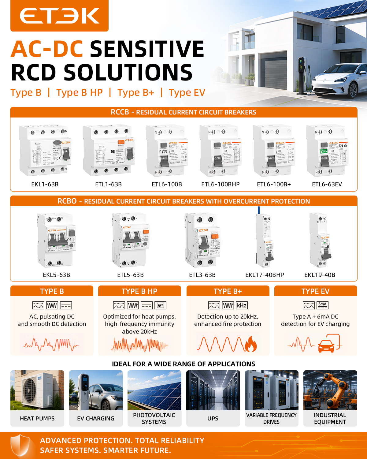
Residual current sensors are typically calibrated for sinusoidal leakage currents at mains frequency. But modern installations rarely present such clean signals. Variable frequency drives, switched-mode power supplies, and LED lighting all introduce harmonics that distort the residual current waveform. A sensor that performs well on a 50 Hz test bench may exhibit significant attenuation or phase shift at the 3rd, 5th, or 7th harmonic. If the protection device relies on that sensor, the result can be nuisance tripping under normal operating conditions or a failure to trip during a real fault.
Matching the sensor to the circuit means examining the harmonic profile before specifying the device. Look at the total harmonic distortion of the leakage current and identify the dominant harmonic orders. Then compare these against the sensor's frequency response curve. For circuits rich in higher-order harmonics, a standard sensor built around a laminated iron core may not be suitable because core losses increase with frequency and can reduce sensitivity. Instead, select a residual current sensor with a ferrite or nanocrystalline core that maintains stable permeability over a wider bandwidth. Also verify the sensor's specified accuracy range—some devices only guarantee performance up to a few hundred hertz, while others are tested to several kilohertz.
Beyond frequency response, consider the waveform type. Residual currents from rectified loads often contain a DC component or pulsed DC, which some sensors cannot detect at all. Type B or B+ residual current sensors are designed to respond to smooth DC and high-frequency AC components, making them a better match for circuits with significant harmonic content. Finally, don't overlook the impact of sensor placement and burden resistor selection. A mismatched burden can further degrade high-frequency response. By aligning the sensor's core material, bandwidth, and detection type with the actual harmonic profile of the circuit, you reduce the risk of both spurious trips and undetected leakage.
Why Standard Trip Tests Miss Real-World DC Leakage Failures
Standard trip tests typically inject a clean DC voltage into a dry, new insulation sample and look for leakage current above a fixed threshold over a few seconds. That approach misses the way real converters impose ripple and switching transients on top of the DC bus. Space charge builds up slowly inside polymer insulation under continuous unipolar stress, locally raising the field until a small void or contaminant starts conducting. The resulting leakage current appears as short, high-frequency spikes that a slow trip unit may never register.
Field failures usually involve moisture, salt deposit, or carbonized dust on the surface. Bench tests don't reproduce those conditions, so surface resistivity can drop by orders of magnitude while the test still passes. Once DC leakage starts across a contaminated surface, it forms a conductive track that keeps growing because the current never reverses to interrupt it. Standard trip curves were designed for AC or smooth DC, not for the harmonic-rich waveforms after rectification.
Trip thresholds also assume the leakage current will rise steadily toward a well-defined limit. In real insulation, partial discharge under DC can occur in bursts, with each burst delivering a tiny amount of charge and eroding the material. The cumulative damage eventually causes a fast puncture, but the individual bursts are far below the trip setting. By the time the breaker sees enough current to act, the insulation has already failed.
Keeping False Trips Low Without Sacrificing Safety Margins
Reducing nuisance trips in protection systems usually means tightening pickup settings or adding intentional time delays, but both approaches can quietly eat into the very safety margins that keep equipment and personnel out of harm's way. A more practical route is to look at the quality of the input signal itself—filtering out transient spikes, inrush currents, or harmonics that are not true fault conditions. By cleaning up what the relay sees, you can lower the false trip rate without moving the actual protection threshold closer to danger.
Another angle that often gets overlooked is coordination between different protection layers. When an upstream breaker trips because a downstream device failed to clear a small fault in time, the upstream setting isn't necessarily too sensitive—the downstream coordination just wasn't tuned correctly. Spending time on proper time-current curve alignment and zone-selective interlocking can eliminate many nuisance trips while preserving the fast, decisive action needed for real faults. This kind of system-level thinking keeps safety margins intact without relying on conservative settings that slow everything down.
Modern numerical relays also offer adaptive logic that was impossible with older electromechanical designs. For example, using voltage restraint or load encroachment supervision on distance elements can prevent trips during heavy load swings that mimic fault signatures. These methods don't reduce sensitivity for actual short circuits; they simply add a second criterion that must be met before a trip command is issued. That extra layer of discrimination is often the difference between a stable process and an unnecessary shutdown, all while keeping the original safety margin fully available when it's truly needed.
Wiring Practices That Prevent Neutral-to-Ground Coupling Issues
Start by treating the neutral conductor as a current-carrying wire, not a spare ground. In every branch circuit, pull a dedicated neutral back to the panel instead of sharing one across multiple circuits. This avoids the subtle voltage drop on the neutral from being imposed on other circuits, which is often the first step toward stray currents appearing on grounding paths.
Keep the neutral and equipment grounding conductors separated everywhere except at the main bonding jumper. Once you leave the service entrance, never tie them together again. Subpanels, junction boxes, and device enclosures should all maintain this isolation. Use separate terminal bars for neutrals and grounds in all downstream panels, and label them clearly so the next electrician doesn't bridge them out of habit.
Route the neutral and its associated phase conductors together in the same cable or conduit. Running a neutral through one metal raceway and the phase wires through another creates inductive loops that can couple noise and voltage onto the grounding system. Also avoid grounding the neutral at multiple points; the single-point ground at the service disconnect is a deliberate design choice that keeps normal return current from finding alternate paths through conduit, building steel, or data cable shields.
Coordinating Time-Current Curves with Upstream Breakers
Getting protection settings right between a feeder breaker and the upstream main isn't just about picking curves that don't overlap. The real trick is making sure the downstream device clears a fault before the upstream one even thinks about tripping, but without sacrificing selectivity for slower arc-flash mitigation. Start by plotting both time-current curves on the same log-log scale and look for the "kiss point" where the feeder's curve touches the main's curve under maximum fault current. If that point sits too far to the right, you'll lose coordination for high-magnitude faults; too far left and you're inviting nuisance trips on transformer inrush.
A common mistake is treating the instantaneous pickup of the upstream breaker as a fixed line. In reality, many modern electronic trip units let you shape that region with a short delay or a definite-time override. Use that to your advantage: give the feeder a 0.1-second head start, and suddenly a bolted fault 50 feet downstream doesn't darken the whole facility. But be careful with the time margin—anything less than 0.2 seconds total clearing time between the two breakers can fall apart under CT saturation or relay tolerance.
When you have a transformer between the upstream and downstream breakers, the inrush current becomes the wildcard. Set the main's instantaneous too low and every energization becomes a dice roll. The better approach is to calculate the maximum inrush point, then verify that the feeder's curve still clears before the main's time-delay band starts. If you can't get a clean separation, consider adding a maintenance mode to the downstream breaker that temporarily shifts its curve upward—this keeps coordination intact during normal operation while giving you one less thing to worry about during a hot swap.
FAQ
The core needs low hysteresis and high permeability across a wide frequency band. If it saturates too early under a DC offset, the sense winding can produce distorted signals that the trip logic misreads as a fault. Manufacturers often use nanocrystalline cores with carefully matched burden resistors to keep the flux swing linear, which helps maintain a stable threshold without oversensitivity.
Beyond the standard 50/60 Hz sine wave tests, reliable verification involves injecting residual currents that combine smooth DC, low-frequency AC, and high-order harmonics typical of variable speed drives. The device should trip within the specified time across this spectrum and not trip when only normal load leakage is present. A good manufacturer will provide test reports for multiple waveform combinations, not just the basic type test.
Type B RCDs often include electronic amplification stages whose gain can drift with temperature. If the threshold shifts upward in cold weather or downward in heat, you either lose protection or get nuisance disconnects. Quality designs use temperature-compensated reference circuits and may specify a derating curve for ambient conditions, especially for outdoor EVSE applications where panels see wide swings.
A genuine Type B unit has a dedicated fluxgate or Hall-effect sensor to capture smooth DC, while Type A only responds to alternating and pulsating DC. If a manufacturer labels a product Type B without this sensor but relies on software interpretation of the AC waveform, it may miss steady DC faults from rectifiers or battery chargers. Check the internal architecture and ask for test results with smooth DC ramps.
The key is to separate normal high-frequency leakage from dangerous residual current. Some designs use a low-pass characteristic in the detection circuit to ignore switching noise above several kilohertz, while others actively filter only the specific harmonics that indicate insulation failure. A well-designed unit also specifies a maximum allowable leakage per phase to avoid accumulating enough to cross the threshold.
It should inject a known residual current through the sensing core, confirm the trip signal reaches the release mechanism, and then reset automatically or keep the contacts open until manual intervention. Basic test buttons that only check the mechanical latch are insufficient for electronic Type B designs. Look for devices that log the last self-test result and can signal an external controller if the test fails.
Because installations differ in the frequency content of residual current. A 30 mA device that trips at 30 mA at 50 Hz might not trip at 30 mA at 1000 Hz unless the standard requires it. You need to check the frequency response curve, the response time at different DC ramps, and the immunity to inrush currents from capacitive loads. A narrowband Type B can give false confidence if the fault spectrum sits outside its tested range.
Multiple chargers can create a cumulative leakage current with components from each rectifier stage. The RCD should be rated for the total expected leakage, not just the individual charger's, and the manufacturer should specify how it behaves with parallel DC sources. Some models include a leakage compensation feature that subtracts known background leakage, but this must be calibrated during commissioning to avoid masking real faults.
Conclusion
Type B RCDs are essential for circuits with DC or high-frequency residual currents that Type A devices simply cannot detect. Unlike Type A, which only responds to sinusoidal AC and pulsating DC, Type B units incorporate detection for smooth DC leakage and mixed-frequency faults—critical in installations with EV chargers, PV inverters, or variable-speed drives. The engineering challenge lies in matching the residual current sensor to the circuit’s actual harmonic profile. A sensor optimized purely for 50/60 Hz will blind itself to the higher-order harmonics that modern power electronics generate. Manufacturers therefore need to specify the frequency response and fluxgate or Hall-effect sensing technology explicitly, not just the nominal residual current rating.
Standard trip tests often miss real-world DC leakage failures because they inject only clean sinusoidal or pulsating DC waveforms, never the noisy, superimposed currents found in field conditions. To keep false trips low without sacrificing safety margins, the RCD’s filtering algorithms must reject transient noise while still responding to genuine DC faults within a defined time-current window. Wiring practices play an equal role: improper neutral-to-ground bonding or shared neutral paths can create circulating currents that mimic residual faults and cause nuisance tripping. Finally, coordinating time-current curves with upstream breakers ensures selective operation—the RCD should trip before thermal-magnetic devices on low-level DC earth faults, but not race them on short-duration inrush events. This balance is where a manufacturer’s true reliability is proven.
Contact Us
Contact Person: Andy
Email: [email protected]
Tel/WhatsApp: +86 13356133008
Website: https://www.etek-china.com/