

OEM UL FM Grooved Butterfly Valve Selection and Installation Best Practices
2026-11-16
Selecting an OEM grooved butterfly valve with UL and FM listings should be straightforward. But between groove dimensions, torque tolerances, and site conditions, plenty of projects still end up with leaks, rework, or rejected inspections. This post lays out the selection and installation practices that separate a clean startup from a callback, with hands-on lessons from DRIFCO.
Why UL FM Listings Are Only the Starting Point
A listing confirms that a product met specific test criteria under controlled conditions, but it never captures the full picture of a real installation. Pipe corrosion, water quality, ambient temperature swings, and installation tolerances all push components into territory the original test may not have covered. Once a device leaves the lab and enters a working system, the assumptions behind that listing start to bend.
The practical risk is rarely a missing approval document. It is the quiet drift between the tested configuration and the field configuration: substituted fittings, different orientation, longer exposure to vibration, or a maintenance routine that falls behind schedule. Each departure may look minor, but combined they can move a system outside the boundaries the listing was based on.
That is why experienced project teams treat listings as a baseline rather than the finish line. They compare the listed assembly against what is actually being installed, document the gaps, and seek manufacturer input or engineering review when the differences matter. The listing opens the door, but it does not settle the harder questions that only emerge after installation begins.
Pressure Ratings That Match the System Instead of the Catalog Cover
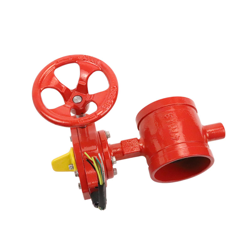
A catalog cover might show a valve rated for 300 psi, but that number often reflects ideal laboratory conditions, not the realities of your piping layout. Pressure spikes from quick-closing valves, thermal expansion, or pump pulsations can push transient loads well above the nameplate figure. When selecting components, the relevant benchmark is the maximum operating pressure at the actual service temperature, plus a margin for surge and water hammer. Ignoring this distinction leads to premature seal wear, flange leakage, or worse, a sudden failure during a routine shutdown.
The same logic applies to hoses, fittings, and filter housings. A component stamped for 150 psi at 70°F may lose more than half its capacity at 180°F, yet system designers sometimes copy the cover rating without checking the temperature derating curve. Instead, start with the pressure profile measured at the pump discharge, the farthest dead leg, and any point where flow stops abruptly. Then select hardware whose working pressure exceeds the highest realistic spike, not the average line pressure. This shifts the conversation from "what does the brochure say" to "what does this system actually demand."
Matching pressure ratings to the system also avoids over-engineering. Buying every component for 600 psi when the line never exceeds 90 psi wastes budget and often increases weight, torque requirements, and installation complexity. A better approach is to map the pressure envelope first, identify the few high-stress zones, and then specify ratings with a clear, documented safety factor for each zone. That way, the final assembly is neither fragile nor bloated, and the pressure class you install reflects the fluid behavior you measured, not a generic number printed on a cover.
Groove Profiles That Catch Bad Pipe Prep Before It Costs You
Most bad welds don't start at the arc; they start at the pipe end. A groove profile that mixes root face width, bevel angle, and eccentricity gives you a hard stop before a fitter burns a joint that should have been rejected. When the profile shows a land that drifts from 0.060 to 0.120 inch in the same quadrant, it is not a setup issue anymore—it is a prep problem waiting to fail.
The profiles earn their keep on the ugly stuff: out-of-round ends, internal undercut, lamination at the bevel, and wall thickness that tapers across a few inches. Instead of catching those after a root pass or during hydrotest, the geometry flags them while the pipe is still on the rack. That shifts the conversation from 'who welded this' to 'let's face it again before we lose the day.'
What makes a groove profile useful is not more data; it is the right data pulled early enough to change the next step. When field welders see the same profile before fit-up, they stop compensating with gap adjustments and start demanding better prep. That one change prevents rework, weld repairs, and the kind of late-project surprises that carry real cost.
Keeping Pipe Weight Off the Valve Body During Fit-Up
During fit-up it is easy to let the valve become a convenient resting point for the spool piece. That is exactly what causes trouble later. Even a modest amount of pipe weight hanging on the flanges can pull the body out of round or twist the end connections enough to create a gap that will not seal. Large gate and butterfly valves are especially unforgiving because their bodies are not designed as structural supports.
The simplest reliable approach is to treat the valve as a floating component until the bolts are tight. Set adjustable stands or chain falls on each adjacent pipe section and lift or lower them until the flange faces come together without forcing the valve upward or downward. Keep those supports in place while the bolts are started and brought up evenly. If you remove the temporary support too early, the pipe often settles back and transfers its full weight straight onto the valve.
Before final torque, check the load path with your hands or a pry bar. The valve should move slightly in its installed position without the pipe springs holding it. Look at the flange gap around the full circumference; it should stay consistent rather than being pinched at the top or bottom. With heavier valves, a second hoist or a balancing sling under the valve body can help maintain position without putting the neck or operator in a bind.
Bolt Torque Patterns That Stop Leaks Before They Start
Most flange leaks trace back to the same oversight: bolts tightened in a circle because it feels natural. That approach pulls one side down while the opposite side lifts microscopically, leaving a gap you won't see until pressure finds it. A star or cross pattern spreads compression evenly, letting the gasket seat uniformly before final torque. Think of it as closing a jar lid with both hands instead of pressing one edge at a time.
The sequence matters as much as the pattern. On a four-bolt flange, you're working in opposites: one, three, two, four. On an eight-bolt flange, it's a staggered star that jumps across the center each time. Torque in two or three passes, never one. The first pass brings everything to roughly half spec, the second to three-quarters, the final to full value. Skipping the intermediate steps invites uneven crush and a leak that shows up weeks later, often after the system has already been put back in service.
Lubrication is the silent variable that ruins even a perfect sequence. Dry threads and lubed threads need wildly different torque values to achieve the same bolt stretch. If the spec assumes one condition and the bolts are in another, you're either under-tightening or over-yielding the fastener. Pick a lubricant, apply it consistently to threads and under the bolt head, and record what you used. Then walk the pattern one final time after the system has seen its first thermal cycle. Bolts relax, gaskets settle, and that last pass is often what separates a dry startup from a slow drip.
A Final Cycle Test That Catches Disc Misalignment
A disc that passes every static inspection can still leave the factory with a slight angular offset that only appears under load. The final cycle test addresses this by rotating the assembly through a complete operational sequence while a fixed probe watches the rim edge. Any wobble beyond a few thousandths of an inch shows up as a rhythmic deviation, and the station flags the part before it ever reaches a vehicle.
What makes the check useful is its timing. By running it after all mounting, torquing, and thermal steps, the test catches misalignment caused by stacked tolerances rather than a single bad component. The readout gives the line operator a clear pass or fail, so there is no need to interpret a vague drift or wait for a downstream complaint.
On the floor, the cycle adds only a few seconds, but it saves rework and field returns. When a disc is slightly out of true, the final test records the runout signature and stops the unit from shipping. That last gate turns a subtle geometric fault into a visible, measurable rejection instead of a noise or vibration problem discovered later by the customer.
FAQ
Check that the valve, not just the body casting, carries the UL and FM marks for the intended system type and pressure class. Match the grooved ends to the coupling manufacturer's listed dimensions, and make sure the seat, disc coating, and stem materials are compatible with the water quality and expected temperature range.
Most listed grooved butterfly valves are rated for 300 psi non-shock working pressure, but the approval is only valid when the valve is used within the listed service limitations. Follow any flow arrow on the body if present, keep the valve fully open during hydrostatic testing, and avoid locations where trapped air or water hammer can impose shock loads.
Leave enough clearance for the handle or gear operator to swing through its full range without hitting walls, pipe, hangers, or nearby equipment. For supervised valves, make sure the tamper switch housing and test access are reachable. A valve mounted with its neck against a column or ceiling often passes visual inspection but fails the practical test.
Forcing pipe ends into alignment, using the wrong gasket grade, and over-torquing coupling bolts are frequent issues. Support the valve body before making up the joints, confirm the pipe ends seat fully into the grooves, and check the gasket is not pinched. After assembly, slowly rotate the disc through its full travel to catch interference early.
The switch sends a supervisory signal if the valve leaves its fully open position, so firefighters are not surprised by a closed isolation valve. Wire it according to the fire alarm panel requirements and test the final installation while moving the handle, not just on a workbench. The trip point should activate after no more than two turns of the handwheel as required by the applicable standard.
Keep the valve exercised rather than leaving it untouched for years. Cycle it fully open and closed at least annually if the system allows, and follow the manufacturer's guidance for cleaning mineral deposits. Avoid petroleum-based lubricants on rubber seats, and replace damaged gaskets or scratched disc edges before they cause leakage.
In most fire protection service the valve is designed for isolation, not continuous throttling. Partial opening can create turbulence, vibration, and accelerated seat wear. If flow modulation is required, select a valve listed for that service and confirm the application falls within the manufacturer's published limitations.
The listing applies to the complete assembly as tested. Swapping in unlisted couplings, modifying the handle, or adding a different actuator can void the approval and create a rejection during inspection. Keep the installation bulletin with the valve records and verify every component matches the listed configuration.
Conclusion
UL FM listings confirm that a grooved butterfly valve has passed baseline fire protection tests, but they do not guarantee it will survive the way pipe fitters actually install it. A valve that looks fine on paper can still leak or bind if the pressure rating was pulled from a general catalog instead of the specific service condition. The smarter approach is to verify the working pressure against the actual system, including surges and pump dead-head scenarios, and to inspect groove profiles before the valve ever leaves the truck. Shallow, out-of-round, or rough-cut grooves create uneven seating and can force the disc to compensate for a bad joint, which shortens seal life and makes the UL FM tag misleading.
During fit-up, pipe weight should never hang from the valve body; temporary supports or jack stands keep the disc from becoming a load-bearing pivot and prevent micro-distortion of the seat. Once aligned, bolt torque needs to follow a crossing pattern in stages, because even a properly listed valve will leak if the coupling is pulled down unevenly. The last step before system acceptance is a full open-close cycle test with flow or at least with the downstream side visible, checking that the disc clears the liner and returns to the closed position without dragging at the stem or seat. This catches misalignment that pressure tests alone often miss and gives the owner a valve that behaves as expected under real operating conditions.
Contact Us
Contact Person: George
Email: [email protected]
Tel/WhatsApp: 13863633883
Website: https://www.es-fire.com