

ODM Electrical Transformer Guide for Efficient Power Distribution
2026-11-17
Efficient power distribution doesn't fail all at once. It erodes through transformers that are slightly overbuilt, slightly undercooled, or simply not designed for the way a facility actually runs. This ODM electrical transformer guide looks at those overlooked mismatches and how they drive energy loss, maintenance cost, and voltage instability over time. If standard catalogs keep missing your requirements, the problem isn't your project - it's the starting point. Lugao develops ODM transformers around load behavior and site conditions, giving engineers a firmer foundation for every downstream decision.
What Nameplate Efficiency Leaves Out
A motor’s nameplate efficiency is usually calculated during a controlled test at full load, steady voltage, and a comfortable ambient temperature. That figure says very little about how the machine behaves when it starts and stops often, sits at 60% load for most of a shift, or deals with uneven voltage from the feeder. Under those conditions, losses move around in ways the label cannot show, and real operating efficiency often settles below the stamped number.
Nameplate data also leaves out the slow effects of wear and repair. Bearing wear, rotor bar damage, a slightly misaligned coupling, or a rewind using different copper can all add mechanical and stray-load losses that never appear on the original plate. Once a motor has been serviced or is working in a hot, dusty room, the factory efficiency number becomes more of a historical reference than a realistic measurement.
Power quality widens the gap even further. Harmonics, phase imbalance, undervoltage, and long cable runs can raise winding temperatures and core losses while the nameplate value stays exactly the same. The label describes an ideal machine under ideal conditions; it misses the ordinary realities that decide how much energy is actually consumed over a year of service.
Matching Transformer Selection to the Load Curve You Actually Have
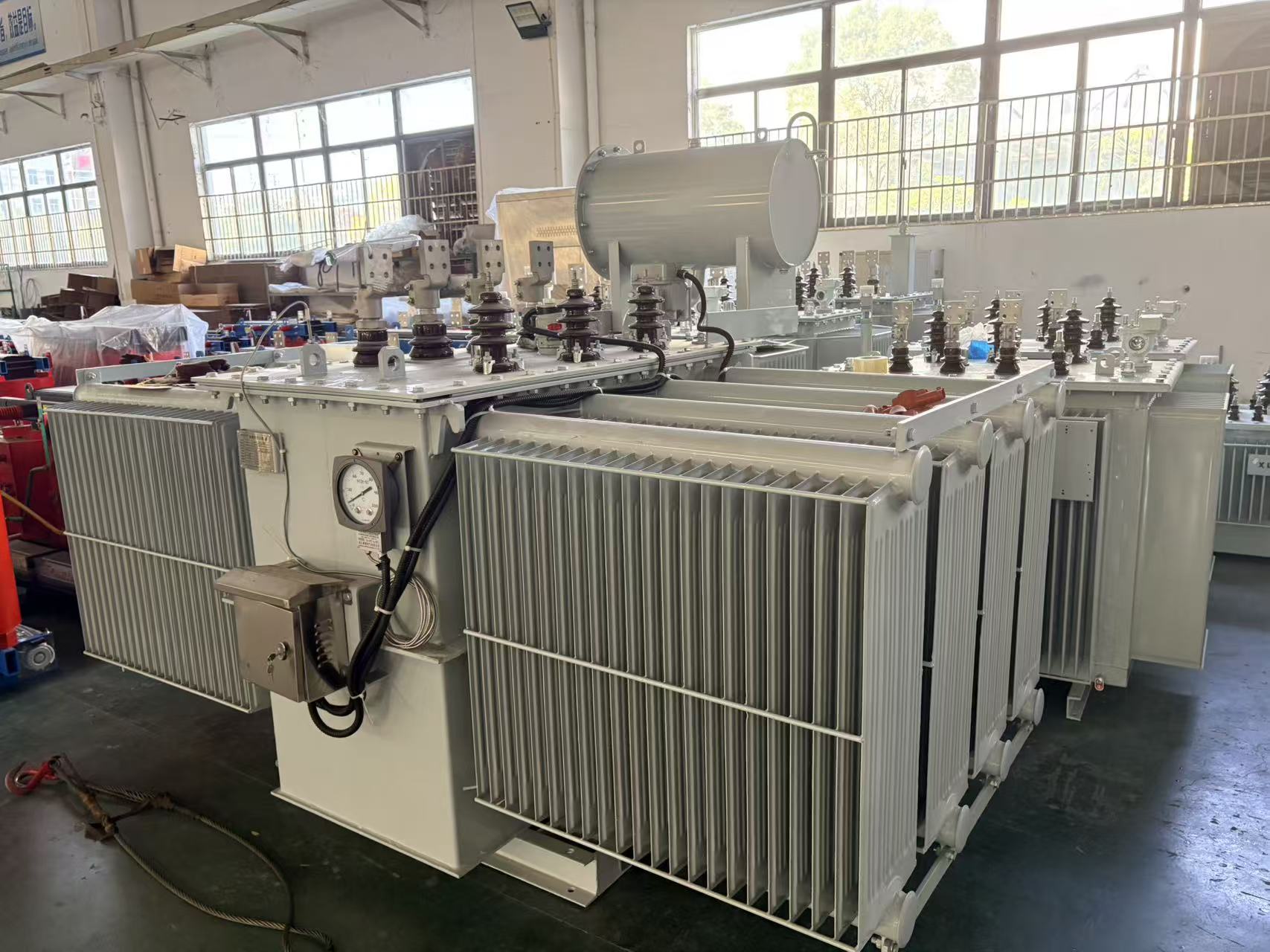
Transformer sizing often falls back on nameplate totals or rough peak allowances, but the actual operating profile matters more than any single number. A load curve that spends long stretches near 60–70% of its occasional peak can tolerate a unit sized closer to the thermal continuous rating, while a sharply spiked curve may need a larger frame or better short-time overload margin just to avoid accelerated insulation aging.
Look at where the sustained load sits, not just the maximum demand. If the curve shows repeated short surges from motor starts or batch processing, harmonic content and mechanical stress can push a transformer beyond what a simple kVA calculation suggests. In those cases, matching the unit to the shape of the curve—rather than the headline peak—keeps hot-spot temperatures within reason without paying for capacity that never gets used.
It also helps to compare the actual daily or weekly profile against the transformer's thermal time constant. Units can absorb brief overloads if the surrounding periods sit low enough to let winding temperatures recover. Reading the curve this way often reveals that a smaller, more efficient unit fits better than the oversized option that a conservative peak-based estimate would recommend.
Why Cooling and Placement Decisions Move the Efficiency Needle
Most efficiency gaps in a data hall are not caused by the cooling equipment itself, but by how air is allowed to move between supply and return paths. When racks are placed without clear hot and cold aisle separation, warm exhaust wraps around to the intake side and drives up inlet temperatures. The cooling system then works harder than the actual heat load demands, even though total capacity may be more than sufficient on paper.
Placement decisions also determine whether sensors and controls see the conditions they are supposed to manage. A temperature probe mounted near a return grille may read higher than the air entering the servers, causing the chilled water valve to open further than needed. Moving that sensor to a representative rack inlet or adding containment panels often delivers a larger efficiency gain than upgrading chillers, because it aligns the control loop with the real thermal load instead of a mixed air signal.
High-density racks should not be treated as a floor-wide average. Concentrated loads create steep temperature differences across a row, and the only practical fixes are local: closer coupling to cooling units, blanking panels, proper cable openings, and sometimes shifting equipment so high-draw systems do not dump heat into low-load aisles. These moves are inexpensive compared with adding mechanical capacity, but they change how effectively every kilowatt of cooling is used.
A Practical Look at Core and Winding Losses in Daily Operation
Core losses rarely announce themselves in dramatic fashion. They show up as a transformer that runs a few degrees warmer than it did last year, or an energy bill that creeps upward without an obvious reason. In daily operation, hysteresis and eddy current losses in the core are always present, but their impact depends heavily on voltage levels, frequency, and the condition of the core joints. A slight overvoltage can push flux density into a less efficient region and make the core dissipate noticeably more heat before anyone thinks to check the incoming supply.
Winding losses are easier to tie to actual load. Because they rise with the square of the current, a modest increase in load can produce a much larger jump in copper loss. A poorly balanced three-phase load or a cable run that forces one winding to carry more than its share will quietly raise losses and shorten insulation life. Measuring resistance at operating temperature, or simply comparing phase currents, often reveals issues that a standard efficiency test at full load would not highlight.
The practical point is not to chase a perfect loss model, but to watch the right variables during normal operation. Core losses tend to stay fairly stable while voltage and frequency remain within limits, while winding losses move with the load profile. Tracking both helps separate harmless seasonal changes from signs of degradation, such as increased no-load current or higher winding resistance. That distinction lets maintenance teams act on evidence rather than guesswork.
Voltage Drop Under Partial Loads Most Planning Overlooks
Most voltage-drop calculations assume the full connected load running at once, so a feeder that looks fine on paper can misbehave when only a fraction of that load is active. A partially loaded circuit does not simply produce a proportionally smaller drop; load type matters more than the total current. For example, a lightly loaded motor feeder may still show a noticeable drop during inrush or when several small switch-mode power supplies draw current in narrow pulses. LED drivers, small VFDs, and electronic ballasts tend to pull non-sinusoidal current even at low average power, and their harmonic content can create a larger voltage distortion than the modest RMS current suggests.
The overlooked part is often not the steady-state value but the range of partial-load conditions a circuit actually sees throughout a day. A design checked only at 100 percent demand may pass with a 3 percent drop, yet the same run may dip enough at 30 to 60 percent load—especially when motors cycle or controls switch banks of lighting on and off—to cause nuisance tripping, flicker, or premature wear in downstream electronics. Planning around a few representative partial-load points, rather than a single worst-case full-load figure, gives a much better picture of how voltage will behave in the real operating window.
Long-Term Efficiency Through Maintenance Choices That Matter
Buying equipment is only the first step. The way you care for it determines whether it remains a reliable workhorse or becomes a recurring headache. Simple habits like clearing debris after each use, checking fluid levels before startup, and replacing worn filters on schedule can extend the life of a machine by years. These small actions rarely feel urgent in the moment, but they quietly prevent the kind of breakdowns that force you to stop mid-task, order parts, and wait for a repair window.
Maintenance choices also shape long-term running costs. A cheap off-brand filter might save a few dollars now, but if it lets contaminants through, the damage shows up later in scored cylinders or clogged injectors. Spending slightly more on parts that meet the manufacturer's specifications keeps the entire system working within its designed tolerances. Likewise, using the right grade of oil for your climate and workload isn't just a recommendation—it affects cold starts, wear rates, and how often you need to top up.
The most efficient operators treat maintenance as a rhythm rather than a checklist. They know which components tend to loosen after a certain number of hours, they observe small changes in sound or vibration before they become failures, and they keep a written log that makes the next service faster. That kind of attention doesn't require advanced mechanical skill. It requires consistency and a willingness to learn the specific needs of the machine in front of you, not just the generic advice in a manual.
FAQ
Efficiency usually starts with the core steel and how the windings are placed. Precision-cut grain-oriented laminations, tight core joints, and balanced conductor sizing cut both no-load and load losses before the unit even leaves the factory.
The nameplate kVA is only one part of the picture. Actual load profile, ambient temperature, harmonic exposure, and expected expansion often matter more. A unit matched to real operating conditions will typically run cooler and cost less to operate than a larger one running lightly loaded.
Impedance shapes how the unit responds to changing loads and faults. Lower impedance helps hold secondary voltage steadier under load swings, while higher impedance limits short-circuit current but may allow larger voltage dips when motors start or heavy equipment cycles.
Cooling does more than protect the insulation. Liquid-filled designs usually move heat away from the windings more effectively, allowing a smaller footprint for the same kVA. Dry-type units avoid fluid handling and are often easier to place indoors, but they may need more space and airflow to maintain the same loading.
A few simple checks catch most problems before they become expensive. Thermal imaging, connection torque checks, keeping ventilation paths clear, and monitoring insulation moisture all help. For liquid-filled units, periodic oil testing gives early warning of contamination or insulation aging.
They are, especially in modern facilities with non-linear equipment such as drives, UPS systems, and large LED lighting arrays. Harmonics add core and winding losses, raise operating temperature, and can shorten insulation life. In those environments, a K-rated or specially designed ODM transformer is the safer route.
It keeps the secondary voltage near the intended level when the incoming supply drifts. That matters because motors, power supplies, and controls all run more efficiently at their design voltage. Small voltage adjustments can reduce losses across the connected load, not just inside the transformer.
A unit that is too large often runs at light load for much of the day. Load losses may drop, but fixed no-load losses continue around the clock. Sizing so the transformer operates in its higher-efficiency band, often between roughly 40 and 70 percent of rating, tends to give the best full-year energy picture.
Conclusion
Nameplate efficiency figures often tell only part of the story, because they reflect controlled test conditions rather than the uneven loads a transformer actually serves. A more useful approach starts with comparing real operating patterns to the unit's load curve, so that the selection aligns with where the equipment spends most of its hours rather than a single rated point. That same practical lens applies to installation choices. Where a unit sits and how air moves around it can shift thermal performance enough to erase or widen the gap between catalog numbers and field results.
Core and winding losses behave differently under daily operation, and partial load conditions can introduce voltage drop that standard planning misses, especially in lightly loaded circuits or long cable runs. Rather than treating these as fixed limits, they are better viewed as signals for adjustment. Maintenance decisions such as tightening connections, checking cooling surfaces, and monitoring load balance tend to have an outsized effect over time. Efficiency, in this sense, becomes less about the nameplate and more about how the transformer is matched, placed, and maintained for the load it actually carries.
Contact Us
Contact Person: Doreen
Email: [email protected]
Tel/WhatsApp: 8618057712366
Website: https://www.liugaopower.com/