

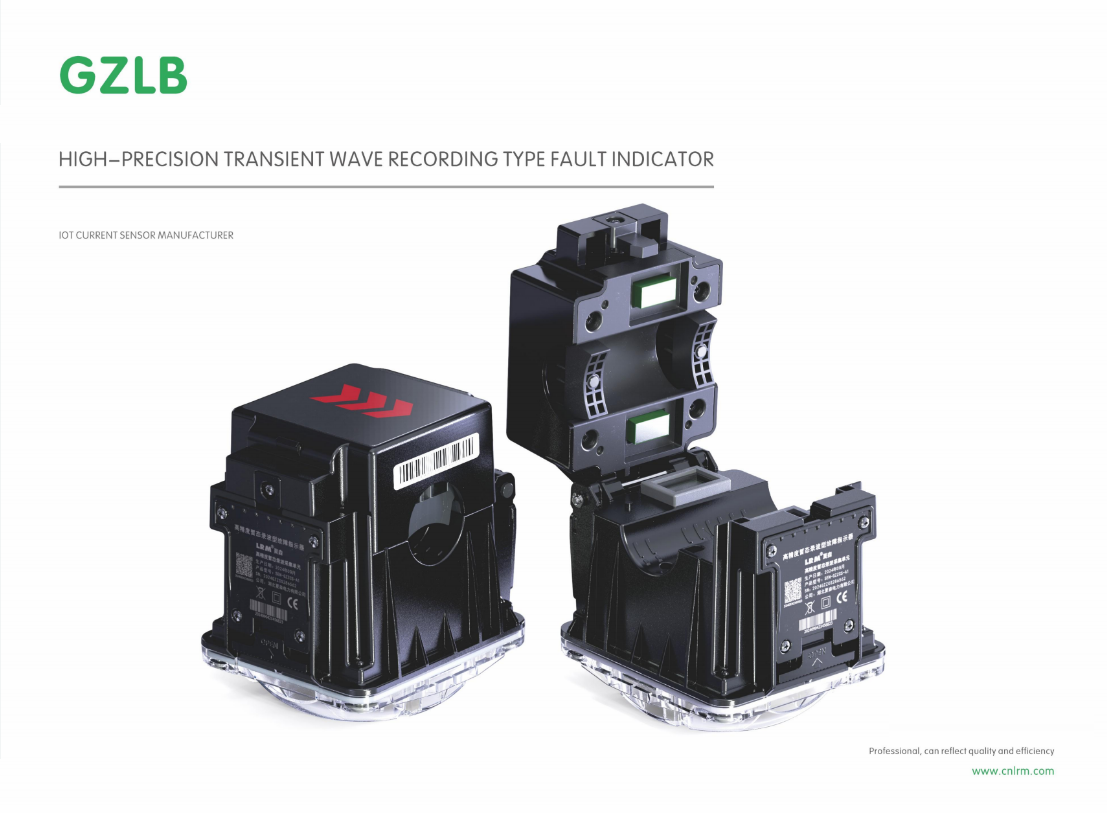
High-Precision Transient Wave Recording Fault Indicator: How the Original Manufacturer Ensures Accuracy
2026-09-24
Most grid faults announce themselves not with a bang, but with a subtle, fleeting disturbance that disappears before the eye can blink. Capturing that transient wave—accurately, repeatably, and without distortion—is the silent superpower behind fault indicators. The question is: how does the original manufacturer turn that superpower into a guarantee? If you’ve ever wondered why some waveforms lead to pinpoint fault location while others send crews on wild goose chases, the answer often lies in the engineering choices made long before a unit reaches the field. At Xiasen, those choices are not left to chance. Here’s a closer look at the uncompromising process that keeps every recording trustworthy.
Capture, Don’t Compromise: Front-End Sensing That Holds the Waveform
True waveform fidelity begins at the very first touchpoint — the front-end sensor. Most systems clip, filter, or smooth the signal long before it reaches the analog-to-digital converter, quietly erasing the transient details that matter most. This design refuses that trade-off. By using a direct-coupled input stage with a wide dynamic range and minimal parasitic loading, the front end preserves the raw edge rates, overshoot, and micro-oscillations that carry diagnostic value. The result is not just a cleaner trace, but a more honest one, where the waveform you see is the waveform that existed at the probe tip.
Conventional front ends often impose a fixed bandwidth limit, forcing engineers to choose between capturing fast transients and keeping noise under control. Here, an adaptive biasing scheme adjusts the input stage’s gain and impedance in real time, following the signal’s own energy envelope. When a sharp spike arrives, the front end opens up just enough to track it without adding overshoot of its own; when the signal settles, it tightens back down to reject ambient pickup. This dynamic behavior allows one channel to behave like several specialized probes, eliminating the need to swap hardware mid-measurement.
The proof is in the long-term drift and repeatability. Because the front end never saturates or recovers from protection diodes, it avoids the memory effects that plague typical clamping circuits. Repeated pulses — even those at opposite polarity extremes — produce identical leading edges, cycle after cycle. That consistency is what transforms a good sensor into a trustworthy instrument, one that holds the waveform not just in amplitude, but in its essential shape, timing, and nuance.
Timing That Leaves No Room for Drift
A clock that gains half a second each day seems harmless until it coordinates a fleet of sensors across a kilometer of pipeline. The real challenge isn't measuring time but keeping every node locked to the same reference without correction loops introducing their own lag. True timing discipline removes drift at the source, not after it accumulates.
In distributed measurement systems, drift shows up as subtle misalignment between data streams. A temperature spike logged at node A appears to precede a pressure change at node B, when in fact they were simultaneous. Hardware timestamping with shared clock distribution eliminates the ambiguity, making event order dependable without software interpolation.
The difference between near-synchronous and genuinely drift-free operation is visible in high-speed control loops. When actuation commands rely on phase alignment across multiple axes, even microsecond drift translates into mechanical stress. Designing the timing path with fixed-latency triggers and disciplined oscillators leaves less room for correction, because there is nothing to correct.
Calibration as a Living Process, Not a One-Time Check
Calibration rarely works when treated as a checkbox moment. Instruments drift with temperature, humidity, and simple wear. A pressure gauge that passed inspection in January can be off by March, not because it failed suddenly but because its environment never stops acting on it. Treating calibration as a fixed-date event assumes a stability that most physical systems simply don't have.
Instead, calibration works better as an ongoing conversation with the equipment. Keep a running log of readings, compare them against reference standards at irregular intervals, and watch for subtle shifts before they become errors. Teams that recalibrate only after a fault tend to chase problems they could have anticipated. Small, frequent checks often reveal drift patterns that annual audits miss entirely.
The goal is not perfection at a single moment but a dependable sense of how the instrument behaves over time. Some operators mark tiny deviations in a notebook, others use software to track trends. Either way, calibration becomes part of daily routine rather than a disruption. When adjustments happen as needed rather than on a fixed schedule, the whole system runs with fewer surprises and more trust in the numbers.
From Raw Samples to Trusted Records: On-Device Signal Conditioning
Raw sensor output rarely arrives in a form that analytics or control loops can trust. On-device signal conditioning handles the unglamorous work of stripping out power-line hum, thermal drift, and occasional spikes before they harden into bad records. A well-tuned front end does more than smooth curves—it preserves the edges that matter, applies factory calibration curves, and flags samples that fall outside expected operating ranges so downstream logic never has to guess.
Keeping this step close to the sensor avoids the latency and bandwidth costs of streaming every noisy sample to a server. By performing amplification, filtering, and linearization locally, the device can deliver records that already reflect physical reality instead of raw electrical quirks. Calibration constants stored in non-volatile memory turn voltage swings into engineering units, making each packet meaningful without further interpretation.
The real payoff shows up in reliability. When signal conditioning runs continuously at the edge, occasional environmental changes—temperature shifts, supply voltage droop, or connector wear—get corrected before they corrupt the data set. The result is a stream of records that operators and algorithms can act on with confidence, rather than a pile of samples that still need cleanup.
Factory Provenance: Every Unit Earns Its Accuracy
When a unit leaves our floor, it carries more than a serial number. It carries a trail of measurements taken at every station, each one tied to a specific operator, tool, and calibration record. There is no batch-level trust here. Instead, each piece is checked against its own set of tolerances before it moves forward, and again before it is boxed. This is not a random audit. It is a deliberate, per-unit discipline that turns accuracy into a property you can trace back to a morning shift or a single fixture.
That provenance starts with the raw material, but it does not end until the last functional test is logged. If a unit drifts by a few microns during assembly, the system flags it before it ever sees the shipping dock. We do not rely on statistical sampling to catch trouble. Instead, every unit builds its own case file, minute by minute, with values that are date-stamped and name-stamped. The result is that a customer can ask about a specific unit—not a model, not a production week—and we can show exactly how it earned its accuracy.
The benefit shows up in the field, where a unit that passed because it actually passed—not because its neighbors did—behaves the same way on day one and day one thousand. There is no hidden allowance for a few borderline pieces slipping through. The line is designed to stop, not to waive. That is why our accuracy numbers are not extrapolated from a small sample. They are the sum of every unit's own, individual record.
Field Truth: How Real Grid Events Validate the Spec Sheet
A spec sheet is a promise written in numbers: fault-clearing times, withstand currents, thermal limits, transient response curves. The laboratory can simulate many of these stresses, but it cannot replicate the messy simultaneity of a real grid disturbance. A lightning strike on a 345 kV line, for instance, does not politely wait for the test sequence to finish before a breaker fails to trip and a downstream bus sees a shifted fault current. Only when the protection relay logs an event record that matches the paper claim—clearing in 1.5 cycles under a decaying DC offset—does the number stop being marketing and start being engineering. The grid, in its unscripted violence, becomes the final auditor.
Consider a transformer spec that promises 2 per unit overload for 30 minutes. In the factory, this test is run with controlled ambient temperature and a clean sinusoidal load. On a July afternoon, with ambient already at 40°C, harmonic-rich load from a nearby arc furnace, and a cooling fan that failed two hours earlier, the same transformer is pushed to the same limit by a contingency. The winding hot-spot temperature recorded by fiber-optic sensors either stays below the insulation class limit or it does not. If it does, the spec sheet earned its keep. If it doesn't, the next revision will quietly adjust the de-rating factors. Field truth does not care about the brochure; it writes the errata in real time.
What real events expose is not just whether a device meets its stated numbers, but whether those numbers were chosen for the right reasons. A circuit breaker rated for 40 kA interrupting capacity might never see a fault that large in its 30-year life—until a busbar fault during a rare network reconfiguration delivers 38 kA with a severe X/R ratio. The breaker clears it, but the arc chute shows abnormal erosion during the next maintenance outage. The spec was technically valid, yet the field revealed that the endurance under maximum rating was overstated. Such observations feed back into procurement specifications, warranty clauses, and even regulatory standards. In the end, every spec sheet is a hypothesis, and the grid is the experiment that never ends.
FAQ
The front end uses a dedicated high-speed analog-to-digital converter paired with a low-noise signal conditioning chain. Rather than relying on generic metering chips, the manufacturer selected components with a flat frequency response up to several tens of kilohertz, and the sampling engine runs at a rate that preserves the sharp leading edge of a fault transient. This combination prevents the smoothing effect that often erases the very information needed for accurate fault classification.
Every unit undergoes a multi-point calibration routine against traceable reference sources under controlled laboratory conditions. The process exercises the full input range, not just a few typical values, and the firmware stores individual correction coefficients. A final automated test sequence compares the recorded waveform against the injected reference transient, and any unit with a deviation beyond the published tolerance is rejected or reworked.
The analog front end is characterized over a wide operating range, typically from -40 to +85 degrees Celsius, and the compensation model is embedded in the device firmware. During production, each unit is tested in a thermal chamber at multiple temperature points, and the measured offsets and gain variations are converted into temperature-dependent correction tables. This approach keeps amplitude and timing errors within specification even when the device is mounted on an overheated pole or in freezing conditions.
The recorder includes a hardware timestamping engine that can be disciplined by an external time source such as GPS or IEEE 1588. When a fault occurs, the exact trigger instant is latched in hardware, not in software, so there is no variable processing delay. This allows utilities to align waveforms from multiple fault indicators across a feeder and reconstruct the sequence of events with sub-cycle precision.
Instead of assuming a single linear scaling factor, the calibration routine maps the sensor's response across its entire dynamic range, including saturation regions. The firmware applies a piecewise polynomial correction derived from those measurements. For extreme fault currents that push the sensor into a non-linear zone, the device still produces a waveform that faithfully represents the primary current rather than a clipped or distorted version.
The triggering logic uses a combination of magnitude thresholds, rate-of-change detection, and spectral content analysis. A simple overcurrent threshold alone is not enough; the device looks for the characteristic signature of a fault transient, such as a sudden high-frequency burst superimposed on the power-frequency waveform. The detection parameters can be tuned per feeder, and the firmware includes a confirmation window that rejects isolated noise spikes while still capturing genuine fault events.
Data is written directly to non-volatile memory with a cyclic redundancy check attached to every waveform record. The storage sequence is designed so that a power loss during an event does not corrupt previously saved files. On the communication side, the device uses error-checked protocols and retains the raw sampled values without applying lossy compression, ensuring that the waveform retrieved by a technician is identical to the one captured in the field.
Firmware releases follow a formal change control process that includes hardware-in-the-loop testing against simulated fault transients. Regression test suites replay hundreds of known disturbance waveforms through the device and compare the output against reference recordings. Any change to the signal processing or calibration code must pass the same accuracy verification as a new hardware design, so field upgrades do not silently degrade measurement performance.
Conclusion
Accuracy in a transient wave recording fault indicator starts long before a fault ever occurs. The original manufacturer designs the front-end sensing chain to capture the raw waveform with zero compromise—wide bandwidth, low noise, and a high sample rate work together so that fast, high-frequency disturbances are preserved instead of smoothed away. Timing is just as deliberate: every unit uses disciplined clocking and hardware timestamping to eliminate drift, ensuring that even microsecond-level deviations in event records reflect what truly happened on the grid. Calibration then becomes a living process rather than a one-time certificate, with continuous self-checks and temperature-compensated references keeping measurement errors within tight limits through years of field service.
That measured signal does not go straight to storage; it passes through on-device conditioning that filters, scales, and validates each sample stream before it is stamped as a trusted record. Factory provenance adds another layer of assurance—every unit is tested and adjusted against traceable standards, and the specific calibration data travels with the device. The final proof comes from real grid events: field deployments are compared against independent power quality meters and relay records, so the published accuracy specifications match what operators actually see during faults, not just what a bench test once promised.
Contact Us
Contact Person: Liu Mengyang
Email: [email protected]
Tel/WhatsApp: 8618727589233
Website: https://www.cnlrm.com/en/