

CNC Press Brake Factory Guide to Precision Sheet Metal Bending
2026-09-23
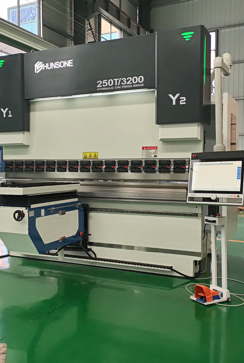
Sheet metal doesn’t forgive vague machine settings. A few microns of ram deflection, the wrong crowning strategy, or a poorly matched backgauge can turn a profitable bend into scrap. That’s why this CNC press brake factory guide goes beyond spec sheets. It walks you through how HUNSONE designs and builds press brakes for real-world bending—covering everything from frame rigidity to tooling compatibility—so you can bring repeatable precision to your floor.
Why Material Grain Direction Changes Your Bend Allowance
When sheet metal is rolled at the mill, the internal crystal structure stretches and aligns along the rolling direction. That alignment isn't just cosmetic—it alters how the material resists deformation. Bending across the grain forces the crystals to separate and slide against each other, demanding more force and a larger bend radius to avoid cracking. Bending with the grain lets the crystals move more easily, so the same tooling produces a tighter, more predictable bend. The practical consequence: your flat pattern and bend allowance must account for this directional stiffness, or the final formed part will miss its dimensions.
The amount of change isn't fixed. In low-carbon steels, the difference between bending across and with the grain might only shift the bend allowance by a few thousandths of an inch per bend. But in higher-strength alloys, aluminum grades, or severely cold-worked material, that difference can grow sharply—sometimes enough to throw a multi-bend part out of tolerance by the last flange. Experienced press brake operators often notice that a part cut from one end of a sheet bends differently than an identical part cut from the same sheet but rotated 90 degrees. That's not operator error; it's the grain direction expressing itself in the springback and the neutral axis location.
To keep bend allowance consistent, you have two practical paths. Either always orient the bend line perpendicular to the grain direction when the part design allows it, or adjust your bend deduction table with separate values for across-grain and with-grain bends. Many shops default to bending perpendicular to the grain for critical dimensions, accepting the slightly larger inside radius in exchange for repeatability and crack resistance. If your parts keep coming out long or short only on certain flanges, check the grain direction before touching the tooling offsets. That single check can eliminate a whole category of dimension drift without changing a single die setting.
Tooling Clearance: The Overlooked 0.2 mm That Costs You Precision
A 0.2 mm tooling clearance often gets treated as a default setting rather than a dimension worth questioning. But in thin sheet metal work, a gap that size can be double the ideal clearance, so the material stretches and rolls instead of shearing cleanly. The result is a punched edge with a ragged burr that demands extra deburring or a die that wears unevenly from the start.
The real trouble appears later, far from the press. Extra clearance lets the stock deform before fracture, so hole positions drift by a few hundredths of a millimeter. In a progressive die, that error compounds across every station, and you end up chasing alignment or blaming the coil when the true culprit is the original gap. It is a silent tax on every part you produce.
Instead of accepting a blanket 0.2 mm, measure each batch of material and adjust the clearance per side. Many shops start around five to eight percent of stock thickness for punching, but alloy and temper shift that number. Keeping a simple log of cut quality against clearance lets you dial in the right figure for each job—and recover the precision that slips away in a fraction of a millimeter most people never think to check.
Bend Sequence Logic for Multi-Flange Parts
When a part carries more than one flange, the bend order stops being a simple left-to-right affair. You have to read the geometry as a chain of dependencies. Some bends can only be formed after others have cleared the way, otherwise the flange hits the tooling or the already-bent section blocks the punch. A practical method is to walk the flat pattern from the inside out, identify which flanges are nested or overlapping, and then assign a sequence that always bends the most constrained feature last.
One common trap is treating equal-length flanges as interchangeable. If two flanges share a corner and both are bent up, forming the shorter one first may let the longer one pass, but reversing that order can lock the part against the die. The rule of thumb is to check the swept volume of each bend. Every flange rotates through an arc, and that arc must remain clear of existing bends, hold-downs, and backgauges. Where interference appears, move that bend later in the sequence or add a relief cut if the design allows.
Tolerance stacking changes the logic again. Multi-flange parts often have a critical dimension between two non-adjacent flanges. If you bend from one end to the other, each intermediate bend adds its own variation, so the final gap can drift. A better logic is to split the part into groups. Bend the flanges that define the datum face first, then work outward from that datum, and reserve the least critical flange for last. This keeps the reference stable and makes it easier to hold the numbers that actually matter on the drawing.
When Crowning Adjustments Outperform Shim Stacking
Shim stacking works fine for coarse leveling, but once you need to tame a specific deflection pattern under a non-uniform load, crowning adjustments take over. A machined crown alters the contact profile continuously across the surface, letting you dial in a pressure distribution that would require a dozen carefully tapered shims to approximate. Those stacked shims introduce micro-gaps and edge effects where each layer meets the next, while a crown blends the correction into the geometry itself. For high-cycle applications or precision sealing, that difference shows up as fewer hot spots, less uneven wear, and a much lower chance of fretting at the interfaces.
Space constraints also push you toward crowning. When a bearing housing or valve body leaves barely enough room for a single adjusting element, trying to fit multiple shims means tighter tolerances, more handling, and higher odds of assembly error. A single crowned component can be ground or lapped to exact spec off-machine, then dropped in without the fiddly trial-and-error of peeling and restacking shims. This becomes critical in field service, where you might only get one shot at the setup before the line restarts. The crown's geometry communicates the intended alignment far more directly than a stack of loose foils ever could.
Thermal stability is another area where crowning wins outright. Shims expand and contract at slightly different rates depending on material, thickness, and surface finish, and under repeated temperature swings they can settle or shift. A crowned surface, cut from the parent material or a matched alloy, moves with the surrounding structure as one piece. Loads stay consistent because there is no stack of independent layers to redistribute themselves. For machines running hot-cold cycles or high-speed rotors where imbalance grows exponentially with eccentricity, that single-piece correction often means the difference between a stable setup and one that drifts out of spec within a few shifts.
Reading Real-Time Angle Feedback Without Overcorrecting
Watching a live angle readout can become a game of chase if every tiny fluctuation triggers a correction. The key is to treat the feedback as a trend, not a command. Instead of reacting to the number the instant it changes, hold the tool steady for a breath and observe whether the deviation persists. Most real-time sensors produce a bit of noise, and chasing that noise leads to overcorrecting that feels jerky and uncontrolled.
A useful mental model is to act like a pilot using an attitude indicator: small, smooth nudges beat large, frequent adjustments. If the angle drifts two tenths of a degree, resist the urge to yank it back. Wait until the drift crosses a personal threshold—say half a degree or a full degree depending on the task—and then apply a deliberately gentle input. This dead zone filters out sensor chatter and keeps your movements fluid.
Over time, you will learn the rhythm of your specific setup. Some tools lag slightly, others overshoot. By paying attention to how the angle responds after a correction, you can build an internal model that anticipates rather than reacts. The goal is not to hold a perfect number every millisecond, but to stay within a working envelope while your hands remain relaxed and decisive.
Springback Mapping for Mixed Batch Materials
Tracking springback across a mixed batch is rarely a single-curve problem. The same nominal alloy can arrive with enough variation in yield strength, work hardening, and thickness that any fixed compensation sends some parts out of tolerance. A practical mapping approach starts by clustering incoming coils into a few property bands, then recording the angular deviation or profile shift for each band after forming and trimming. Those measured offsets become the basis for a lookup table rather than a universal overbend value.
Once the initial map is built, it needs to be treated as a living dataset. New coils are assigned to the closest existing band based on quick incoming inspection data, and occasional destructive checks or inline scans update the local springback response. The advantage shows up most clearly in operations that mix lots from different suppliers or heat numbers on the same line: the press or roll former can pull the right adjustment from the map before the first part is even measured, reducing trial pieces and hidden scrap.
A less obvious payoff comes from anomaly detection. If a coil labeled as standard suddenly behaves like the high-strength end of the map, the deviation itself flags a material mismatch or a processing drift. Over time, the mapping data can be fed back into tolerancing decisions, showing whether tighter incoming specs or a wider compensation range is the cheaper way to keep the mixed batch within profile.
FAQ
A CNC press brake closes the loop between commanded position and actual ram position. Instead of relying on mechanical stops that drift after repeated cycles, the controller monitors linear encoders and adjusts hydraulic flow in real time. That lets the machine hold ram depth within a few microns, which is the difference between a 90-degree bend and a 90.4-degree bend on thin stock.
Back gauge fingers set the distance from the bend line to the edge of the blank. On a modern CNC brake, those fingers move on ball screws and servos, so positioning error stays under ±0.02 mm. More importantly, multiple gauge axes can tilt, lift, or retract between bends, letting the operator keep a reference edge against a fixed stop through the whole sequence. That consistency is what keeps a 500-part batch within tolerance.
Springback is proportional to the ratio of yield strength to elastic modulus. Stainless steel has a higher yield strength but a similar modulus to mild steel, so it springs back more than aluminum, which yields at lower stress. A factory can compensate by overbending a few degrees, but the exact correction changes with batch, grain direction, and even temperature. The practical approach is to store measured springback values per material lot in the CNC controller so the ram depth adjusts automatically for the next run.
When the ram pushes down on a long die set, the bed and ram deflect slightly in the middle. That makes the bend angle shallower at the center than at the ends. A crowning system, either mechanical shims or hydraulic cylinders under the die, applies counter-pressure to flatten the deflection curve. Without it, you can easily see a 1- to 2-degree angle difference on a 3-meter bend. With automatic crowning, the machine measures the load and adjusts in real time.
The V opening should be roughly eight times the material thickness for most structural work, but for tight tolerances you need to go narrower, sometimes down to six times thickness or less. A smaller V increases tonnage but reduces the radius and creates a sharper, more stable bend. The rule of thumb is to keep the inside radius close to the material thickness; if the radius gets too large, the bend angle becomes more sensitive to hardness variation from sheet to sheet.
Hydraulic oil cleanliness matters more than most shops admit. Contaminated oil causes the proportional valves to stick or overshoot, which shows up as random angle drift. Beyond that, checking ram parallelism with a dial indicator, keeping the back gauge rails clean, and re-torquing die clamp bolts after every shift prevents the slow shifts that ruin a production run. Many factories find that a weekly laser alignment check catches problems before they appear in parts.
The order of bends determines where the part contacts the ram and how residual stress redistributes. If you fold the outside flanges first, the middle bends become harder to reach and the part may twist. A better approach is to work from the inside out, or to alternate bend directions so the blank doesn't curl. On CNC machines, the control can simulate the bend sequence and flag collisions, but the real trick is to keep at least two reference edges against the back gauge for as long as possible.
Conclusion
In precision sheet metal bending, the difference between a clean part and scrap often comes down to details that are easy to overlook. Material grain direction is one of them: bending across the grain produces a different bend allowance than bending with it, yet many shops program the same deduction for every blank. A practical CNC press brake factory guide treats grain orientation as a variable to verify before setup. Tooling clearance adds another layer—just 0.2 mm of unintended gap between punch and die can shift the angle enough to fail a tolerance check, especially on thin material. When a part has multiple flanges, bend sequence logic becomes the unsung hero; ordering bends from inner to outer flanges, or using relief cuts and staged tooling, prevents collisions and distortion that no amount of angle correction can fix.
On longer bends, crowning adjustments generally outperform shim stacking because the deflection curve changes with die load and material width. Rather than chasing a flat bed with physical shims, a press brake operator can use the machine's crowning system to compensate dynamically. Real-time angle feedback is valuable, but it invites overcorrection; the guide should recommend setting a tolerance band and only adjusting when the measured angle falls outside it. For mixed batch materials, springback mapping becomes essential—two coils of the same grade can behave differently due to heat or supplier variations. Instead of one fixed springback table, a factory-level approach logs test bends per batch and adjusts targets accordingly. These practices, taken together, turn routine bending into a controlled process.
Contact Us
Contact Person: James Chen
Email: [email protected]
Tel/WhatsApp: 86 13770803946
Website: https://www.hunsone.com/